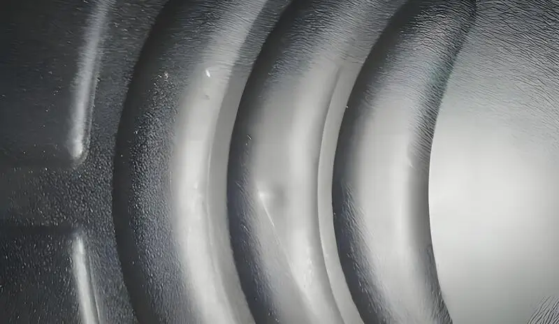
In high-requirement production fields involving liquid silicone rubber (LSR) products—whether precision medical device components, premium baby products, or demanding sealing parts—a common “aesthetic killer” frequently emerges: unnatural glossy patches on the product surface, halo-like gloss rings around ejector pin areas, or cloudy, mist-like marks in thick sections.
These defects not only downgrade the perceived product quality, but may also trigger customer complaints and concerns over process stability and reliability. Many practitioners mistakenly assume such issues are exclusive to thermoplastic injection molding. In reality, this assumption misses the mark. As a thermosetting material, LSR follows a distinct surface stress formation mechanism, with causes and solutions that differ fundamentally from those of conventional plastics. Addressing these issues therefore requires a dedicated technical understanding and targeted countermeasures.
This article deliberately sets aside interference from other materials and focuses exclusively on LSR material characteristics and molding principles. It aims to systematically deconstruct the root causes behind surface gloss variations and haze marks, and to provide a comprehensive solution framework spanning product design through mass production.
1. Phenomenon Identification: More Than an “Aesthetic Issue,” but a Visual Signal of Internal Stress
First, we must accurately identify the problem. Stress-related surface marks on LSR products typically manifest in three distinct forms:
Localized Glossy Spots / Gloss Streaks
Most commonly observed around ejector pins, insert edges, or parting lines, these defects appear as reflective areas with a surface texture noticeably different from the surrounding regions.

Hazy / Cloudy Marks
Typically appearing in thickness transition zones or at the flow-end regions, these marks give the surface the appearance of being covered by an uneven, mist-like layer.

Hazy / Cloudy Marks
Typically appearing in thickness transition zones or at the flow-end regions, these marks give the surface the appearance of being covered by an uneven, mist-like layer.
What Is the Essence of These Phenomena?
These are not simply stains or physical scratches; rather, they are the visual manifestations of residual internal stress within the product.
We can understand it this way: when internal stress develops in LSR for various reasons, it causes subtle changes in local material density and the microstructure of the polymer network.
These changes disturb the path of light scattering and reflection, much like ripples on water distort the way light passes through. As a result, we perceive differences in gloss and texture. In simple terms, the “glossy spots” we see are actually the internal stress “illuminating” itself.
二. Root Cause Analysis: Three Exclusive Origins of LSR Stress Marks
To understand why these marks “glow,” we must delve into their origins. The stress marks in LSR products primarily stem from three core causes:
01. Cause 1: Chemical Crosslinking Shrinkage Stress
This is the fundamental source of stress in LSR. The curing of LSR is based on the hydrosilylation reaction, which inevitably involves volumetric shrinkage. The key point is that if a product exhibits uneven wall thickness or non-uniform mold temperature, different regions will cure and shrink at different rates, generating mutual tensile stress within the material.
These stresses tend to release at the weakest structural points or the most visible surfaces, manifesting as observable marks. They are commonly found in thickness transition zones or on surfaces corresponding to internal structures (e.g., ribs or bosses).
02. Cause 2: Demolding Adhesion and Ejection Stress
LSR has extremely high surface adhesion. If the ejection system is improperly designed—for example, ejector pins that are too small, unevenly distributed, or have rough surfaces—or if draft angles are insufficient, the huge peel-off force during ejection can locally stretch or distort the product surface, creating marks that appear like “skin being pulled and shining”. This is the main reason for gloss around ejector pin marks and slider traces.
03. Cause 3: Flow-Induced Curing Stress
Although LSR has low viscosity, it still exhibits rheological behavior. Improper gate design or uneven mold temperature can lead to inconsistent curing rates at the flow front. Material contacting the hot mold wall first may start crosslinking prematurely, while subsequent material is still flowing. This “timing mismatch” results in flow marks and density variation bands.
At the same time, fillers or base polymers may experience slight orientation under shear forces, forming optically non-uniform regions after curing. These are commonly observed near gates and at runner convergence points.
三、 Preventive Design: Product and Mold Strategies
Solving the problem begins with prevention, which is more effective than remediation. Introducing the following principles during the design stage can significantly reduce the risk of stress marks at the source.
01. Product Design Guidelines
Wall Thickness Uniformity (Primary Principle): Aim for consistent wall thickness. Any unavoidable thickness variations must use gradual transitions with large radii, strictly avoiding abrupt changes.
Comprehensive Filleting: All internal corners, rib bases, and boss roots must be designed with adequate fillets (recommended radius R ≥ 0.5 mm) to eliminate stress concentration points.
Structural Optimization: Rib thickness should generally not exceed 50% of the main wall thickness, and ensure sufficient draft angles for demolding (typically ≥ 1°).
02. Core Mold Design Principles
Gate System Selection:

Mainstream Reliable Choice: Optimized Cold Runners
This is the most common and high-quality option for LSR. The design focus is to ensure sufficient runner dimensions (typically diameter ≥ φ6 mm, depending on the product) so that low-viscosity LSR flows smoothly without premature curing in the runner, while maintaining a balanced layout.
High-End Precision Choice: Valve-Gated Cold Runners
For applications demanding zero flash, flawless appearance, and balanced filling—such as medical transparent parts—this represents the ultimate solution. It allows synchronized or sequenced control of all gates, fundamentally reducing flow inconsistencies and gate shear stress, although it comes with higher cost and technical complexity.
Ejection System:

Ejector Pins:
Ensure sufficient number of ejector pins with the largest possible diameters, positioned in thicker or more rigid areas of the part.
It is strongly recommended to apply special coatings to ejector pins and cavity surfaces (e.g., Ni-PTFE composite plating), which can reduce demolding forces by over 60%. This is one of the most effective methods to prevent gloss marks caused by ejection.
Temperature Control System (The Soul of an LSR Mold):

Temperature Control System (The Soul of an LSR Mold):
Use high-precision mold temperature controllers (temperature variation within ±1°C), and design balanced cooling/heating channels to ensure that temperature differences across the cavity surface do not exceed 2°C. Any “hot spots” can cause premature localized curing, leading to shrinkage stress.
Venting System:

Venting System:
Provide sufficient and continuous venting slots (depth 0.001–0.003 mm) to prevent trapped air from causing localized curing defects and weld lines, which are also potential contributors to stress marks.
四、 Process Fine-Tuning: Coordinated Optimization of Molding Parameters
Once the product design and mold are finalized, process fine-tuning becomes the final step of refinement.

01. Key Process Windows
Injection Phase: Use medium-to-high injection speed (avoid too slow, which causes hesitation, or too fast, which causes jetting) to ensure the material front advances smoothly and uniformly into the cavity.
Curing Phase: Mold temperature is the decisive variable. Within the allowable range of the material, slightly increasing and maintaining extremely stable mold temperature helps promote uniform crosslinking, reducing shrinkage differences. Curing time must be sufficient to ensure complete reaction.
Demolding Phase: Employ multi-stage ejection patterns, such as “fast-slow-fast,” to allow the product to leave the cavity smoothly. External mold release agents should be used cautiously; if necessary, select LSR-specific types and apply in precisely controlled micro-amounts.
02. On-Site Debugging Priority Sequence
Following the steps below can efficiently resolve stress mark issues:
Verify Mold Temperature Uniformity: Use a surface thermometer to carefully check the actual temperature at various points in the cavity.
Optimize Injection Profile: Focus on adjusting injection speed and the V/P (velocity-to-pressure) switch point to eliminate visible flow defects.
Inspect the Ejection System: Check ejection balance, confirm ejector pin surface conditions, and consider applying or enhancing surface coatings.
Fine-Tune Curing Time: Find the optimal balance between complete vulcanization and production efficiency.
五、 Surface Stress Marks on LSR Products: Quick Diagnostic and Action Checklist
| Defect Location | Primary Suspected Cause | Key Checks & Countermeasures |
|---|---|---|
| Ejector Pin / Insert Edge | Localized Glossy Spots | Ejection System1. Ejector Pin Design: Check pin size and layout balance; prioritize increasing pin area.2. Surface Treatment: Ensure ejector pins and cavity surfaces have effective mold-release coatings (e.g., Ni-PTFE).3. Draft Angle: Confirm sufficient draft angle (typically ≥1°). |
| Wall Thickness Transition Zone | Hazy / Cloudy Marks | Design / Temperature Control1. Product Design: Check for abrupt wall thickness changes; optimize with gradual transitions using large radii.2. Mold Temperature Uniformity: Use a thermometer to measure cavity surface and eliminate hot spots; ensure ΔT ≤ 2°C.3. Cooling Efficiency: Verify that water channel layout is reasonable and unobstructed. |
| Near Gate / Flow Direction | Gloss Streaks / Uneven Gloss | Filling Process1. Gate System: Check gate size (not too small) and design balance.2. Injection Profile: Optimize injection speed to avoid jetting or hesitation; adjust V/P switch point.3. Mold Temperature: Confirm and stabilize mold temperature; avoid over- or under-heating in gate areas. |
六、 Specialized Materials: A Solid Backbone for Process Optimization
Beyond process and mold optimization, the core performance of the material often plays a decisive role in addressing LSR stress marks. When the process window is narrow, a specialized material with lower shrinkage, improved demoldability, and higher batch-to-batch consistency can significantly mitigate stress effects from the source.
Jvtech Silicone focuses on LSR material development and provides customized material solutions to address surface defects such as stress marks:
Optimized base polymer and crosslinking system to achieve more uniform internal stress distribution
Special formulations that balance flowability with tear resistance
Dedicated grades for high-transparency parts, thin-walled components, and other specialized applications
We believe that excellent surface quality arises from the deep integration of material science and applied processing techniques. Jvtech Silicone is committed to providing professional material solutions to help you overcome technical bottlenecks. For technical inquiries, please contact: +86 13424592517.